Carrier board 1 for CN1 APM 
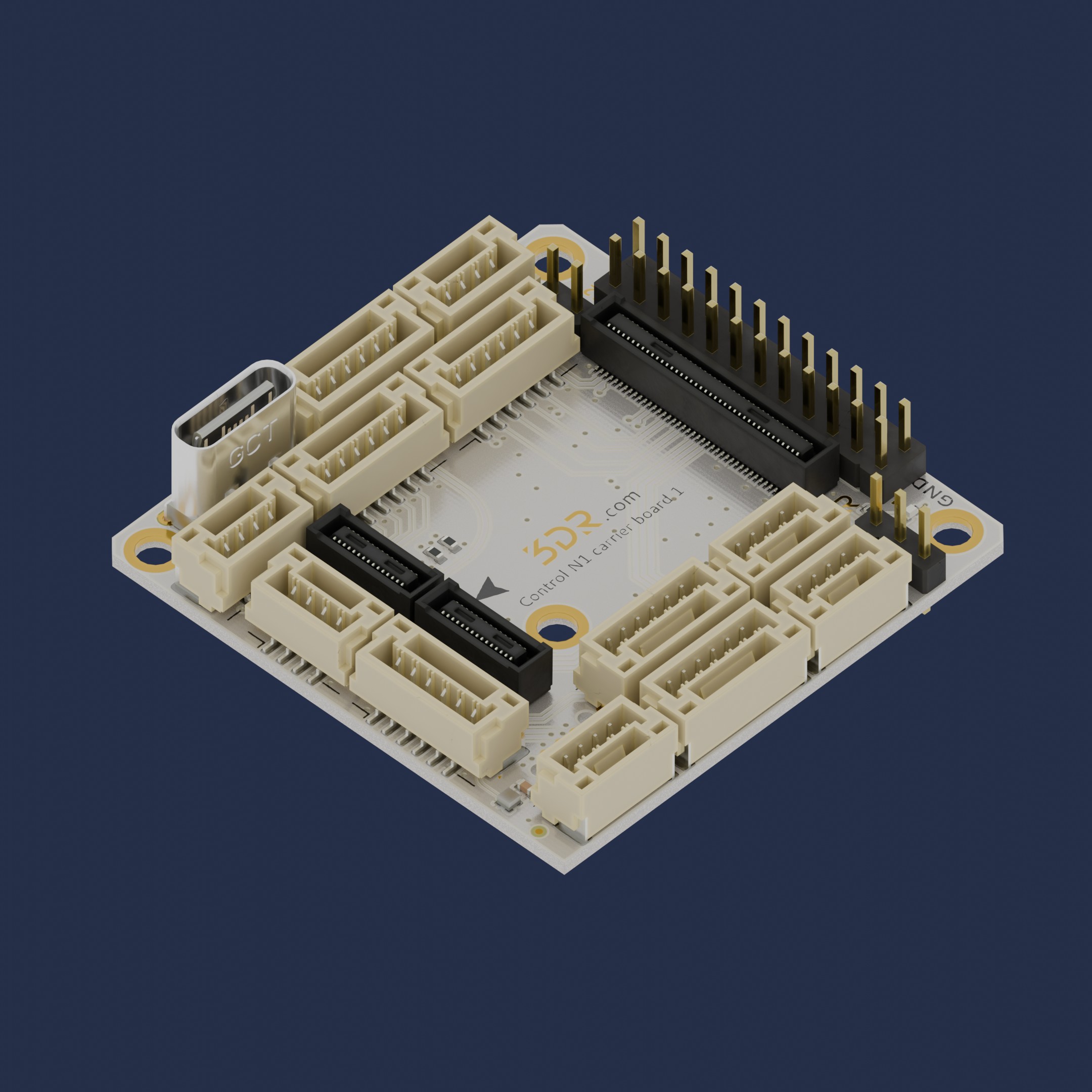
The square form factor CN1 Carrier Board “Cuby” (R0026) is a compact platform for our Control N1 board.
Whether used as a standalone module or clustered with other units, the square geometry offers flexibility, consistency, and ease of integration across a wide range of environments.
Built on over 10 years of flight controller design and development experience.
Key Features
- Baseline Control N1 compatibility without any additional adapters
- Stable Footprint - long term commitment
- Basic power management - single 5V power supply for FC and peripherals
3D View
Use Cases
- Surface-mounted installations requiring uniform spacing
- Control panels or enclosures with modular layouts
- Grid-based systems where multiple units are deployed together
- Applications where reach is secondary to stability and compactness
Installation & Setup
- Unpack the unit and verify all components are present.
- Position the square module in the designated mounting area.
- Connect the Control N1 (R0026) using the integrated interface, press firm and equally against the carrier board.
- Secure the unit using screws, adhesive pads, or magnetic mounts as applicable.
- Power On the system and verify operational status.
Warning
Always refer to the safety and compatibility guidelines of Control N1 before installation.
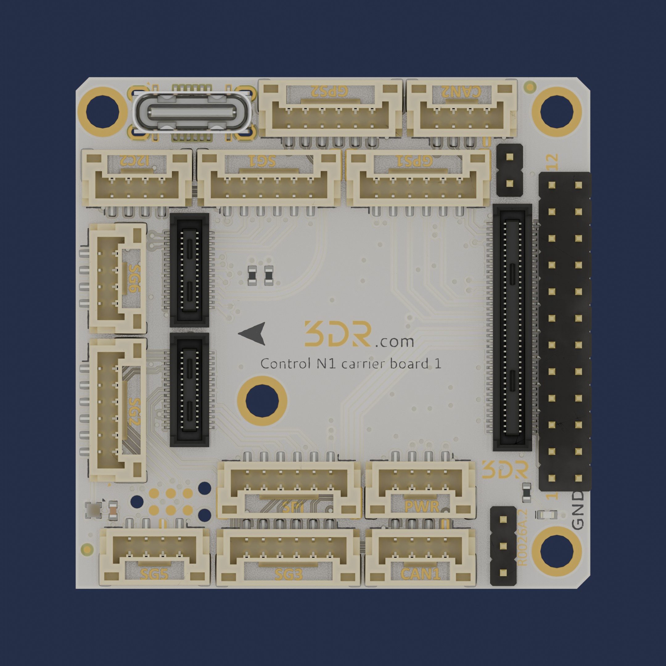
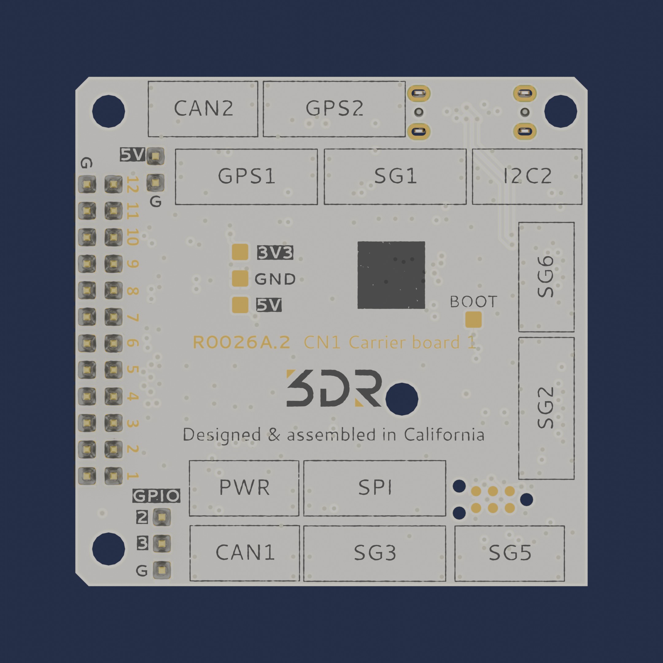
Available Ports
- USB
- GPS1 (SG7 + I2C1)
- GPS2 (SG4 + I2C2)
- Serial 1 (SG1) w/Control Flow
- Serial 2 (SG2) w/Control Flow
- Serial 3 (SG3) w/Control Flow
- Serial 5 (SG5)
- Serial 6 (SG6)
- External SPI (SPI)
- I2C2 (I2C2)
- CAN1 (CAN1)
- CAN2 (CAN2)
- POWER (PWR, ADC1 + ADC2)
- ADC1 (ADC1)
- ADC2 (ADC2)
- SWD CLK/IO/RST (compatible w/ TC2030 connector)
- Servos (12 x PWM, BIDIR capable)
- IOs (3x GPIO)
To have a more detailed description of each pin, please use our Pinout tool.
Pinout tool
| Port | Name | Pin |
|---|---|---|
| USB | 5V | x |
| USB | USB_DM | x |
| USB | USB_DP | x |
| USB | GND | x |
| GPS1 | 5V | 1 |
| GPS1 | UART5_TX | 2 |
| GPS1 | UART5_RX | 3 |
| GPS1 | I2C1_SCL | 4 |
| GPS1 | I2C1_SDA | 5 |
| GPS1 | GND | 6 |
| GPS2 | 5V | 1 |
| GPS2 | USART3_TX | 2 |
| GPS2 | USART3_RX | 3 |
| GPS2 | I2C2_SCL | 4 |
| GPS2 | I2C2_SDA | 5 |
| GPS2 | GND | 6 |
| SG1 | 5V | 1 |
| SG1 | USART2_TX | 2 |
| SG1 | USART2_RX | 3 |
| SG1 | USART2_CTS | 4 |
| SG1 | USART2_RTS | 5 |
| SG1 | GND | 6 |
| SG2 | 5V | 1 |
| SG2 | UART4_TX | 2 |
| SG2 | UART4_RX | 3 |
| SG2 | UART4_CTS | 4 |
| SG2 | UART4_RTS | 5 |
| SG2 | GND | 6 |
| SG3 | 5V | 1 |
| SG3 | UART7_TX | 2 |
| SG3 | UART7_RX | 3 |
| SG3 | UART7_CTS | 4 |
| SG3 | UART7_RTS | 5 |
| SG3 | GND | 6 |
| SG5 | 5V | 1 |
| SG5 | USART1_TX | 2 |
| SG5 | USART1_RX | 3 |
| SG5 | GND | 4 |
| SG6 | 5V | 1 |
| SG6 | USART6_TX | 2 |
| SG6 | USART6_RX | 3 |
| SG6 | GND | 4 |
| SPI | 5V | 1 |
| SPI | SCK | 2 |
| SPI | MISO | 3 |
| SPI | MOSI | 4 |
| SPI | CS | 5 |
| SPI | GND | 6 |
| I2C2 | 5V | 1 |
| I2C2 | SCL | 2 |
| I2C2 | SDA | 3 |
| I2C2 | GND | 4 |
| CAN1 | 5V | 1 |
| CAN1 | CAN1_H | 2 |
| CAN1 | CAN1_L | 3 |
| CAN1 | GND | 4 |
| CAN2 | 5V | 1 |
| CAN2 | CAN2_H | 2 |
| CAN2 | CAN2_L | 3 |
| CAN2 | GND | 4 |
| PWR | 5V | 1 |
| PWR | ADC1 | 2 |
| PWR | ADC2 | 3 |
| PWR | GND | 4 |
| ADC1 | ADC 1 | 1 |
| ADC2 | ADC 2 | 1 |
| SWD | 5V | 1 |
| SWD | SWDIO | 2 |
| SWD | RST | 3 |
| SWD | SWDCLK | 4 |
| SWD | GND | 5 |
| SWD | NC | 6 |
Mechanical information
| Mechanical specfications | |
|---|---|
| Dimensions | Width: 38.4mm (1.51″) Length: 38.6mm (1.52″) Height: 8.5mm (0.33") |
| Weight | 4.4g (0.16oz) |

Downloads
Maintenance
- Wipe clean with a soft, dry cloth
- Avoid exposure to moisture or corrosive substances
- Inspect mounting points periodically for wear or loosening
- Store in original packaging when not in use to prevent damage